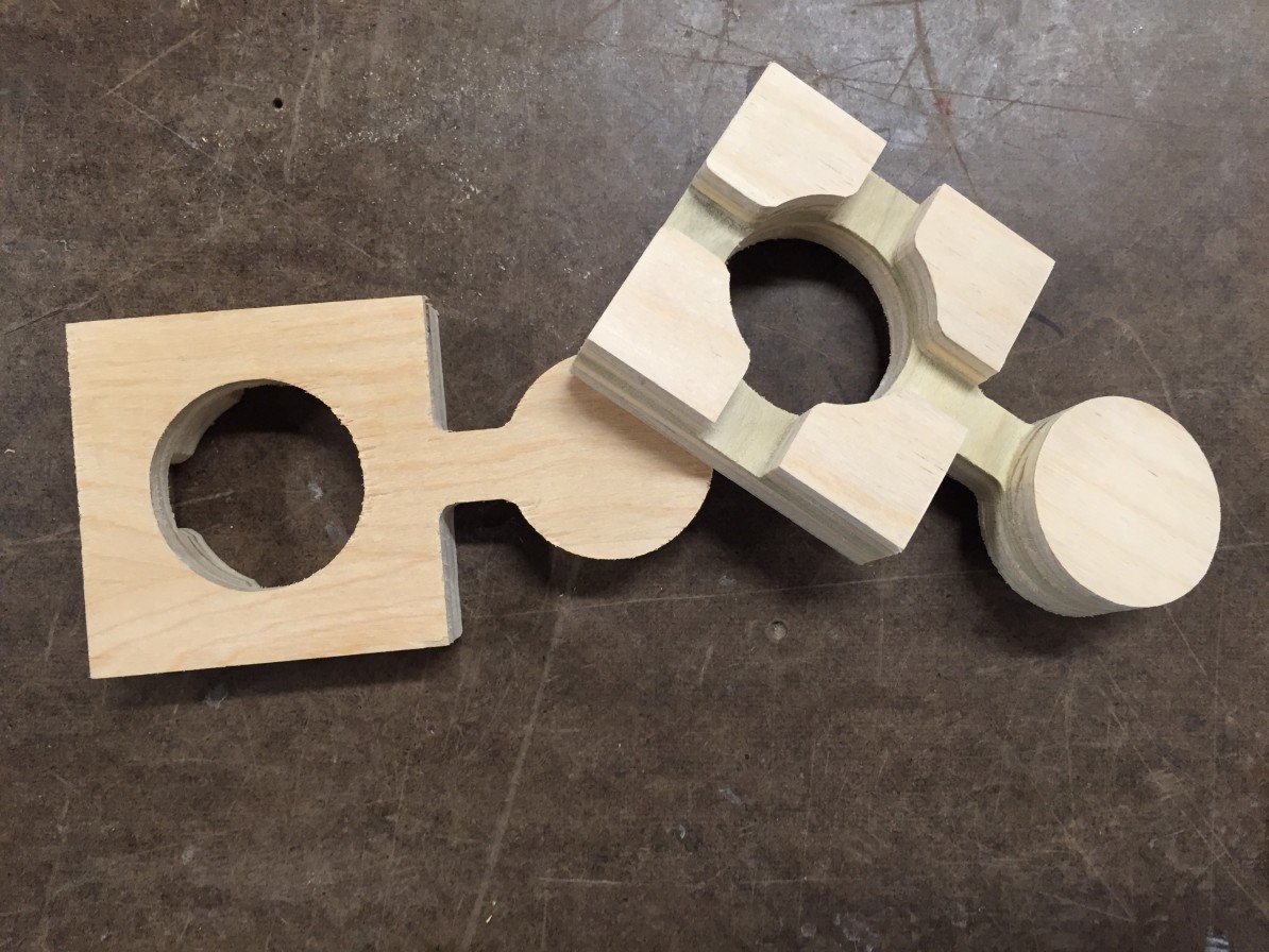
Two weeks ago we were given the challenge to create joints that connect with one another. This might sound like a trivial task (it did to me in the beginning), but actually, it’s not. When creating pieces that are meant to fit together, it’s important to remember that even though in theory it makes sense that these two pieces will just naturally fit into one another, in reality they most likely will not.
Every material has a different tolerance, which means that every material will need a different negative space for the positive piece that will be inserted to it.
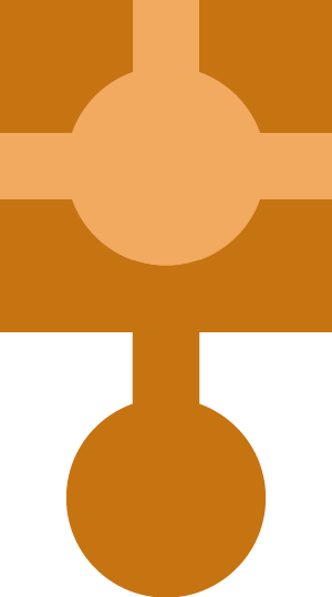
This is an sketch of what I attempted to make:
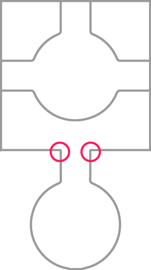
And, ideally, I wanted these joints to be possible:
The material I used was plywood, so I knew that I would have to make the hole a bit bigger for the piece to fit in. Assuming this would be my biggest issue, I went ahead to view my file on MasterCam, however, the preview kept showing me problems if I were to go along and cut my file on the CNC. All the issues I was having had to do with misinterpreting the path of the drill bit and it’s abilities to produce straight shapes as opposed to rounded corners. This is a bit hard to envision at first, because when we think of cutting a straight line, that’s usually a very trivial task. With the drill bit though, you always have to remember that it can’t cut anything with sharp corners, because the bit itself is actually a tiny circle. So, areas like this are virtually impossible to cut using the drill bit:
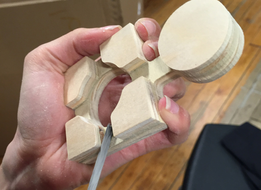
So since those corners actually came out rounded, you can imagine that it is impossible for the rounded corners to lock into the joining parts where the corners there are sharp. Conclusion? The design should have round corners everywhere. By the time I had realized this it was a bit late to cut these again, so I ended up sanding the corners down:
This ended up taking a lot longer than expected, but the pieces successfully linked together!


1 Comment